4.3 Physical layer Interfacing
EIA-232 (AKA RS-232) is a mess!
DTE = Data terminal equipment.
Computers and terminals are usually DTE (but sometime not!)
DCE = data circuit-terminating equipment (e.g. modem)
DCE xmits and rcvs bits in the channel, it also communicates with the DTE. A priori knowledge of the DCE rcvr-xmitter pair is needed. See fig 4.8
The interface has 4 parts: Mechanical, electrical, functional and procedural.
Mechanical: Shape of the plugs...and pin outs.
electrical: voltage levels and timing. Codes (e.g. NRZ-L)
Functional: (wiring function) data; control; timing and ground
procedural: event sequences.
RS-232 (1962 EIA=Electronic Industries Association).
RS-232-C (1969) = connector independent spec
RS-232-D (1987) connector dependent spec. See fig 4.9
Electrically: 1=-3 or less, 0=3 or more wrt gnd.
R<20kbps, distance < 15 m
Functional Spec:
data
control
timing and gnd. Full-duplex is possible since there is both an RxD (also RD) = received data and TxD (also TD) = transmitted data. Flow control in full duplex is soft (stx and etx chars are defined (cntrl s and cntrl q)). Half-duplex flow control is hardwired. The procedural Spec = protocol. (see fig 4.11)
On power up:
DTE asserts DTR (20).
DCE asserts DSR (6)
On carrier sense, DCE asserts CD(8)
DTE asserts RTS (4) when it wants to send
DCE replies with CTS (5) if it is ready to take data
Connecting two computer (DTE) using RS-232-C is an interface problem.
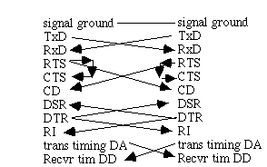
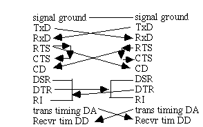
The problem is solved by connecting them with a null modem
this causes the crossing of several wires. Stallings null mdm
with hrdwr hndshk and clk.


In practice there are no guarantees that your DCE or DTE will work this way. You MUST read the manuals (or test or guess) to perform the interface.
From the DTE pin 20 is an output, from the DCE pin 20 is an input. by convention, pins and signals are named and discussed from the point of view of the DTE. So TD means pin 2, by default.
Outputs have a (!) and inputs have a (?). For example:
These are the official names (unofficial abbreviation). The names of the signals and their pin numbers are the same but there is a functional difference. Sometimes the is on RTS (request to send) and CTS (clear to send).
There is also RS-422 in common use. R=230,400 bps. External clocking enables R=920,000 bps. RS-422 is like RS-232c but is balanced. RS-423 is like RS-422 but is unbalanced. Again physical connectors are all different. E.g. 128 KB, 512K and 512 KE Mac had a 9 pin D-connector for RS-422. Mac Plus and later, SGI indigo and others have 8-pin mini-DIN.*** WARNING !!! ***
The DB-25 on the back of a Macintosh is NOT a serial port! It is a SCSI parallel port. Any attempt to use this connector as a serial port will NOT function correctly and may cause damage to the Macintosh and/or the equipment being connected.
The two serial ports of a Macintosh are mini-Din-8 connectors which are labeled with a telephone (the "modem%20port" ) and a printer ( "printer%20port" ). Functional specs are like the RS-232-c, DCD (data carrier detect), DTR (1), CTS (2), RxD- (5), RxD+ (8), TxD- (3), TxD+ (6), ground (signal (4) and chassis (shell)). There is also a clock input for the 920 kbps xmission.
IBM PC/AT and PS/2 uses a 25-pin D connect.
To interface the RS-422 to the RS-232 -c you throw out the RxD+ and the TxD - from the RS-422.
DIN-8 MALE DB-25 MALE
GROUND 4 O--+--------------------O 7 GROUND
RxD + 8 O--+
RxD - 5 O-----------------------O 3 RD
TxD - 3 O-----------------------O 2 TD
Hsko 1 O--+
Hski 2 O--+--------------------O 20 DTR
In RS-232 data signals are inverted (marking is minus) control signals are not (marking is plus). Thus the TxD- signal drives the modem.
Leave TxD+ disconnected, grounding this will short out a driver. Similarly the RxD from DCE is inverted, it can drive the Mac's RxD minus line, but in this case the RxD+ line is grounded to prevent any extraneous signals from being induced into the circuit. We are drive both HSKi and DTR from HSKo so the problems `described above can happen. An alternative arrangement would drive these
signals from the modem/DCE's source of DSR, like this:
+--O 6 DSR
Hsk IN 2 O--------------------+--O 20 DTR
Some modems require RTS:
+--O 6 DSR
Hsk IN 2 O--------------------+--O 20 DTR
+--O 4 RTS
Finally, if you have only 3-wire cable and don't need DTR handshake, you can wire each side like this:
HskOUT 1 O--+ +--O 6 DSR
Hsk IN 2 O--+ +--O 20 DTR
+--O 4 RTS
Macintosh to terminal (or other DTE device):
DIN-8 MALE DB-25 FEMALE
GROUND 4 O--+--------------------O 7 GROUND
RxD + 8 O--+
RxD - 5 O-----------------------O 2 TD
TxD - 3 O-----------------------O 3 RD
Hsk IN 2 O-----------------------O 20 DTR
The same analysis applies with respect to the data signals, except that in this case the RxD and TxD are switched. RxD+ is grounded, TxD+ is disconnected. For this particular cable we have wired the terminal/DTE's DTR back into the Macintoshes HSKi to implement a hardware handshake. Assume the terminal side is a printer that is being overrun. One of the things these printers can do is drop DTR. By wiring it through to the handshake input we make it possible for the Macintosh software to temporarily pause in sending, until the printer's buffers empty out and the printer reasserts the DTR signal. Some terminal devices may need to see DSR (Data Set Ready) or CD
or CTS , in which case they may be driven
+--O 20 DTR
This is probably appropriate +--O 6 DSR
for a communications terminal +--O 8 CD
in which DTR is a totally static signal and does not move.
+--O 4 RTS
+--O 5 CTS
or
+--O 4 RTS
This is probably appropriate +--O 6 DSR
for a printer that flaps DTR +--O 5 CTS
as the buffer fills and empties. +--O 8 CD
The logic is to drive from whichever of DTR or RTS is NOT flapping around as buffers fill and empty or as the terminal transmits and receives... To connect directly to an IBM PC we believe CD must be asserted. That is, an IBM PC will not accept data unless it also sees the CD signal.
E.g. to interface the IBM PC to the MAC mini-DIN:
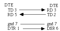
Mac 8-pin din on left, DCE on Right.
The DTR-> DSR is not needed if (XON-XOFF) is used.
also the IBM PC needs lines 6,8 and 20 (DSR, CD and DTR) wired together. Why? DTR is output by the PC into DSR and CD to fool the PC into thinking the modem is on and the carrier is present. Beware, 25 pin D connectors can be used for ANYTHING!! E.g. apple:SCSI, IBM serial, parallel?!, video!! etc...
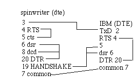
Sometimes auxiliary signals are used to indicate extra signals (e.g. out of paper on a spinwriter).
To further simplify interface life: RS-449 (1977)
RS-449 = mechanical, functional and procedural standard.
RS-449 has signal ground, send common and receive common, TxD, RxD, RTS, CTS, DSR, DTR, RI (ring indicator) etc. It is like RS-232-C (and CCITT V.24) with 30 pins (on a 37 pin connector). Rs-232-c defines 21 signals (on a 25 pin connector).
Nobody seems to use RS-449.
Implementation for RS-232-C can be performed in software. E.g. 68HC11 uses software to drive the parallel lines into RS-232-C emulation. This limits the speed of the line to 9600 baud, but saves on the cost of an external UART.
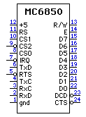
The UART is the hardware method for performing RS-232-C conversion of parallel data. For example, the MC6850:
The 6850 is an ACIA (asynchronous Communicatinos Unterface Adapter. D0..D7 are bidirectional data lines (just like RAM). CS0..2 are chip selects, RS is a register select (two read-only, two write only). Thre is one enable line (E) one R?W line and seven data and data control lines (RXC TXC DCD RTS RxD TxD and CTS.
X.21 is like RS-232-C but uses a smaller set of wires (8 with a 15 pin connector) Control wires are mux'd. X.21 is used as the physical layer for X.25 protocol.
It should be clear that there is advantage in removing the questions of physical layer interfaces from the higher-level aspects of networks.